

Shendrones Siccario Frame Kit with Gel Damper
Giá bán: 9,350,000 VNĐ
VIDEO mới nhất
Siccario
You know how car companies roll out a new model annually, so they give it a chance to sell for a year before rolling out something better? Yeah, we don’t do that. Five minutes after Gab perfected his Thicc he asked for something new.
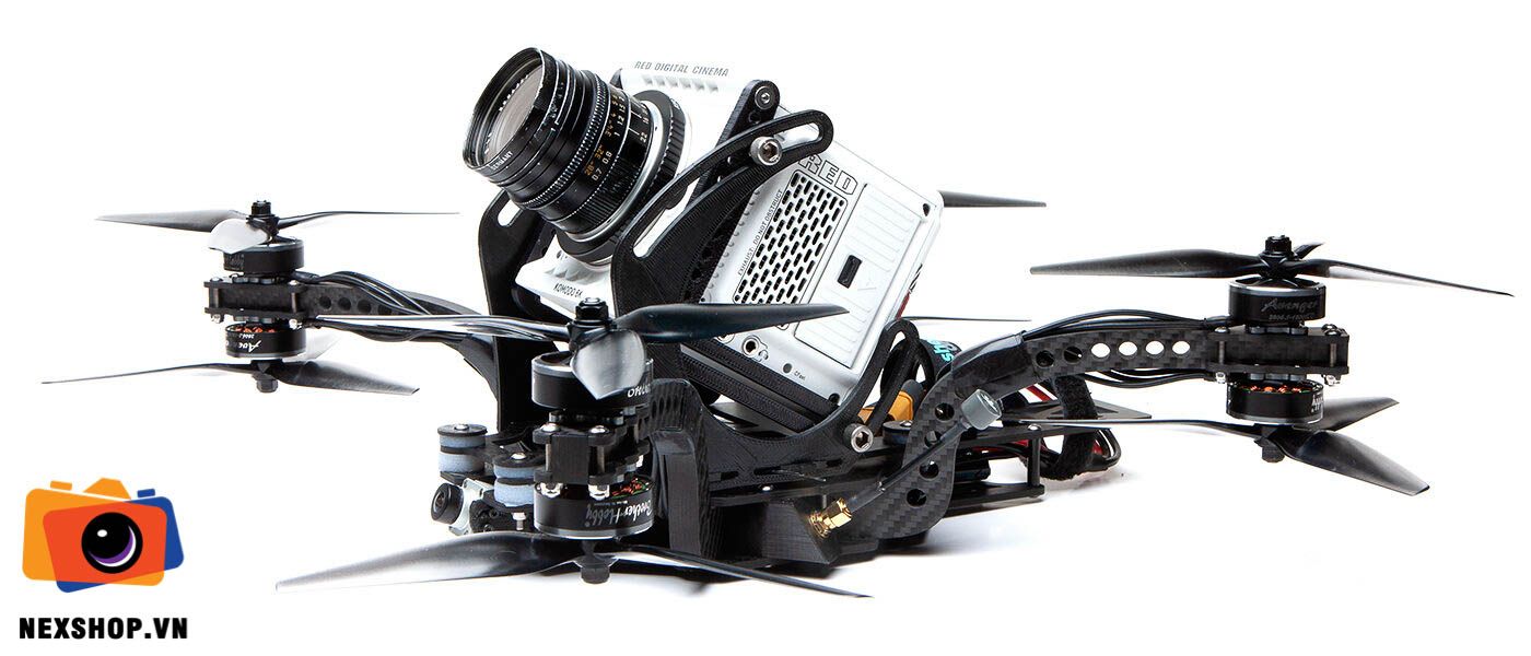
Gab wanted something that could take advantage of the Z Cam’s slim form factor, by nestling the cam between the props for prop free video at 0 or even negative tilt, Gab’s preferred way to shoot downhill sports. This would also tighten up rotational mass for better handling.
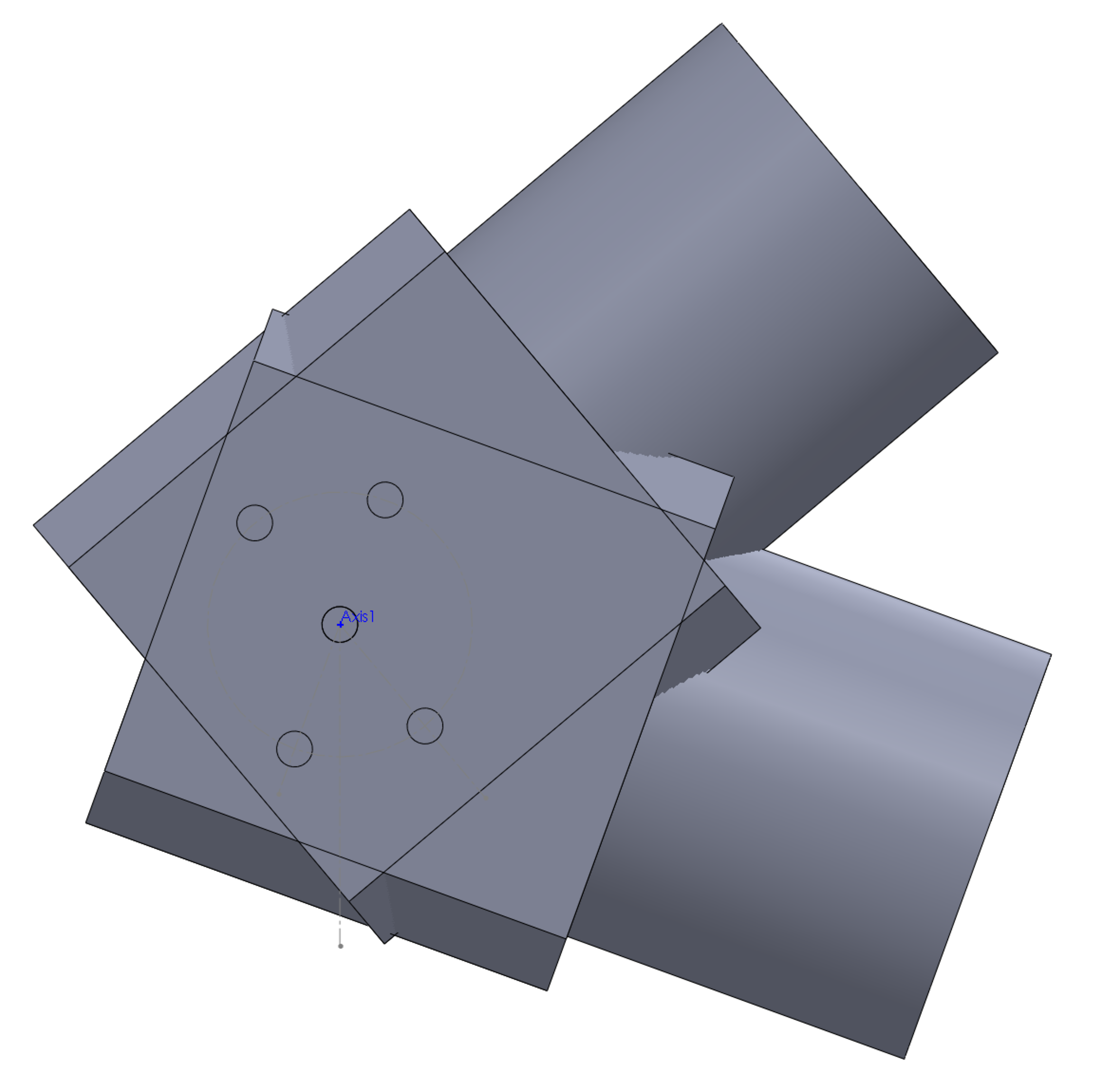
The center of thrust on an X8, unlike a quad, goes right through the middle of the arms. So if you want to put the camera right in line of the center of thrust, well, you got a problem. So I thought of this:

Now the tough part is, how do you make that arm? The easiest way would be to cut it out of 10mm carbon, then drill mounting holes along the carbon layup.

Unfortunately, that would cause the carbon to delaminate, so we’re going to have to do this the hard way, with interlocking pieces a la box frames. I originally conceived of arms made of two vertical 4mm pieces with cross braces, but fortunately Gab asked ‘why not just make it a single 10mm piece?’ Duh.
The Thicc motor layout flies great so we’re starting with that. We know the front of the lens has to be approximately in line with the front motors for unobstructed video. With the battery behind the cam, this works out almost perfectly for CG. The Z Cam has side mounting holes, which are great for changing cam tilt. This also means the cam plate can be parallel with the top plate, which will make experimenting with dampers much easier. This also gives us a simple blank canvas for the cam plate so we can accommodate different cameras. With those parameters established it was time to get crackin’.
A 20mm stack was enough for the components in Thicc, so I made the arms 20mm tall. The sandwich plates will be 3mm – I couldn’t imagine anything thinner being strong enough.

I wanted the ends of the arms to be a thin as possible, but cutouts for motor screw heads shave off some material, so I could go only so thin.

Four M3’s hold the motor mounts in place. The screws are tangent to the sides of the arms so they lock the plates in laterally as well.
With the arms done it was time to move to the sandwich plates. I prefer flowing lines but I couldn’t get it to look right.

So I went for a more geometric look, and it made much more sense here.

I added the overcuts (round bits can’t cut square inside corners) and this thing’s starting to take shape.

Gab likes how Hydrophobe’s waterproofing makes it a real workhorse, so he asked for the same feature here. Oh boy. I proposed putting a heatsink in back, away from the high stress area around the arms. It would nestle in a relief cut in the carbon, and protrude a half mm above the surface to mesh with a tpu skirt. Two esc’s mount to the heatsink with thermal paste in between, while the fc mounts to the carbon, right in the center of the frame.


Bottom view, the aluminum is exposed to the air for cooling.
Then I added mounting points to screw the heat sink on.

So that’s the main frame sorted. I went ahead and ordered the carbon to make sure the frame is airworthy first, while continuing to brainstorm the cam mount/damping solution. Gab ordered a Z Cam and had it sent to me so I could take measurements.
I did a rough mockup to see how much clearance we’d need for 40 degrees uptilt and 20 down.

Since this frame’s all about tightness and perfect CG, it really bothered me that we’d have to raise the camera 20mm to accommodate the tilt, so I started thinking about a sliding slot system that will keep the camera as low as possible at all angles, and this is what I came up with, using the top and bottom holes.
Then I changed it to using the middle hole and bottom hole instead, which makes the part smaller, locks the camera on a vertical track, and, bonus, it looks like it’s giving you the finger.

We want some fore/aft adjustment to accommodate different lens barrel lengths and fields of view, so I’m hoping the tension from screwing in the camera will be enough to clamp the cam plate and lock the vertical stanchions in place. We’re always concerned with quick adjustments on shoots – you don’t want the crew waiting on you while change cam tilt. This system, if it works, would be really simple. Loosen the camera, set your angle and fore/aft, and re-tighten four screws to lock it all down.

A couple M3’s on the tabs keep the stanchions from falling off but don’t keep them from sliding.
I’m holding off on the cam plate ‘til we figure out the dampers. We might need m3 screw holes, we might need great big grommet holes. Meanwhile, the carbon came in. It’s a bit nerve wracking to cut interlocking parts since tolerances are so critical. Too tight and you’ll be filing, too loose and things are floppy. Luckily I guessed well and everything fit together nicely.


Coupla M4’s clamp down the arms. I didn’t want to take any chances with M3’s. Like the motor mounts, the bolts are tangent to the arms so they brace them laterally as well. It’s rock solid once tightened down.
The frame turned out to be a bit heavy, about 500g, or about 80g more than Thicc. There’s lots of spots for weight savings, so round two could be much lighter.

I keep forgetting about the motor wires. It’s super snug and unbelievably annoying to get those two nuts on, but thankfully it all fits.

I thought I was super slick with those zipties, but it turns out the lower prop hits the wire and ziptie under the arm. Half the motor wires need extending. We’re going to have to ask Brother Hobby for longer wires.

This thing’s a bit of a nightmare to build since you can’t assemble it until you have it all wired up. Zipties hold the arms in place while you build. I opted to forego waterproofing for now so I stacked the esc’s. If I’d mounted the second esc behind the first one I’d have to extend the signal wires to the fc, and that’s just too much splicing for one build.

So. Much. Soldering. I left all the wires super long ‘cause it’s a proto and you never know what’s going to change. I went with my trusty double xt60 parallel battery setup so I don’t have to buy big batteries.
I got MMCX to SMA extensions to get the antennas out as wide as possible. I drew up SMA mounts which lean up against the arm so the antenna can’t rotate into the props.

Good thing I left the wires long. If I build it again I’d have cable routing sorted much better. With the antenna mounts on there’s no access to the fc’s usb (foreshadowing).
I had initially dropped a CLI dump from my Thicc on to this fc, but I wasn’t able to get an rx connection. I thought it might be a Betaflight 4.2 vs 4.1 issue, so reset all the settings and started fresh. It didn’t work. Luckily Troy Naquin saved the day – I had the wrong baud rate set for the Air Unit. Finally it was all set up and ready to be assembled.
Closing it up was an adventure, as you can imagine. You have four floppy arms you have to simultaneously drop into their slots while making sure no wires get pinched in the process. I got it done with a couple helping hands from my daughter.
I took it out for a quick maiden, and immediately realized that it had stock pids – I neglected to change the pids when I reset the fc. It still flew pretty well but a little slop was definitely evident. I brought it home and went through the arduous process of opening and closing it (I managed it solo this time) to get the Thicc pids on there.

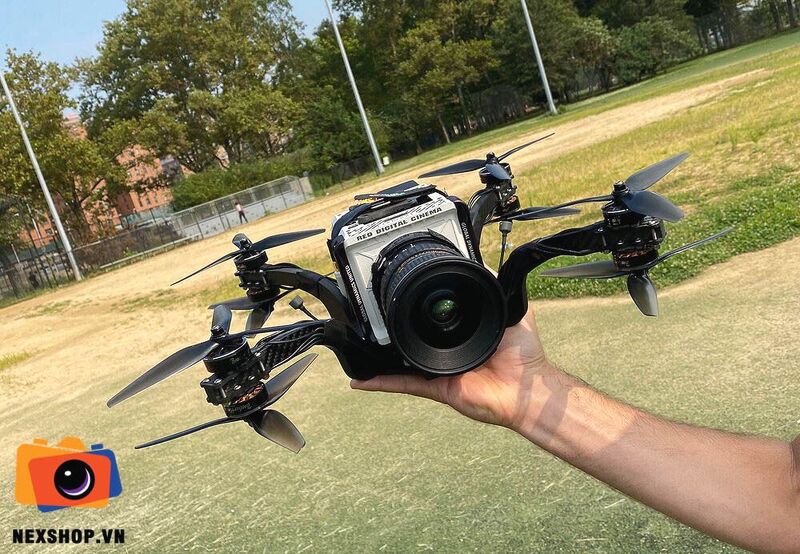
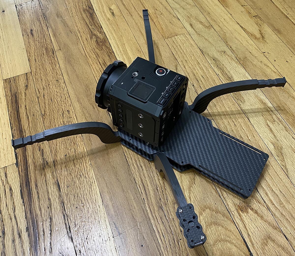
This thing’s so bizarre looking in the air.
Here it is the next day. The fields were all locked up so I had to fly it easy in this open spot. That’s Justin telling me to get it in the sun and kick up some dust.
And here’s some more aggressive flying the next day, good to see the frame hold together just fine.
Gab got his and confirmed that he likes the way it flies, time to move to the cam mount situation. He’s been working insanely hard at finding a perfect damping solution on Thicc, and we’ll be taking advantage of all the knowledge he gained in the process here.
He roughed in the camera and battery to test for unobstructed video and balance, and we found that my initial guess was a bit off. The camera will sit a bit more forward, so for round 2 I’ll have to extend the nose a little bit. We also figured that the front damper mount points could be a bit more spread out, so the nose will be a bit wider as well.

We decided the damper design would basically be a big grommet, just like fc grommets. The pass through hole will be 9mm, and the outer diameter about 18mm. With those dimensions I drew this up.

I also started to put it on a diet. The main frame will go through extensive changes once we learn everything we can from this iteration, so only the arm gets work for now. I like this geometric progression. The holes will be handy for cable routing as well, a good way to keep them away from props.

I’ve never had a frame so fundamentally tied to a camera before, so that it only looks right with the camera mounted. I dropped in a rough render of the zcam just to see it all together.


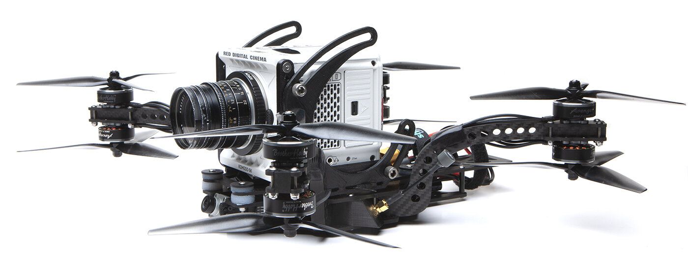
Gab got his cam mount cut locally by CNC Madness and finally we got to see this baby in its full glory.

I mocked up a cross section of the Zcam to confirm that my clamping system would work.

Gab confirmed that it flew well, but a bit heavy. We put our heads together and listed all the changes for V2:
Extend and widen the front damper mounting points. Allow more forward travel for the camera to allow for unobstructed video at negative tilt.
Lose weight: add holes to arms, narrow the tail, mill out the 3mm plates where strength isn’t needed.
Heat management: Gab found a filament (TCPoly Ice9 Flex) that can work as a heat sink, so we’re losing the aluminum plate. We might even switch to Kotking instead of a TPU skirt for waterproofing, in which case we won’t be enclosing the electronics and won’t need heatsinks.
V2
With those changes in mind I got back to work. I originally thought the second esc would be mounted to the aluminum in the tail, which meant the tail had to be pretty wide. Now we’ve moved both esc’s up a slot so the tail isn’t housing anything any more, so I narrowed it way down to the width of a 3300mAh battery. The bottom plate only needs to extend halfway down the battery, more weight dropped.
I extended the top plate for the front dampers, and gave them a full 16mm circle for the grommets to rest upon.

Narrowing it down.


If you look carefully you can see the milled out parts in the two big plates.

If we go with the 3d printed heatsinks they’ll be here.

First test print. This stuff conducts along the layer lines so you have to print this piece vertically so the filament will bring the heat from the inside to the outside.
I had six frames cut. The carbon bits came in and I hurriedly swapped my parts over. But when I tried to screw down the motor mounts I couldn’t get the locknut threads to engage, and that’s when I noticed that my arm drawings were messed up! The little recesses for the screw heads were missing, which means the motor mounts were floating a mm or two above the arms. What a stupid and costly mistake.

No grooves, just sadness.


Chuyên máy ảnh, phụ kiện Sony Alpha Nex
- Địa Chỉ: Số 10 - Ngõ 12 - Phố Trần Quý Kiên - Quận Cầu Giấy - Thành Phố Hà Nội
-
0868417786
- Email: okharon@gmail.com
- Giới thiệu
- Hướng dẫn mua hàng
- Chính sách bảo mật
- Chính sách đổi trả và hoàn tiền
- Chính sách vận chuyển và giao nhận
- Chính sách thanh toán
- Cam kết
- Thông tin khuyến mại


Copyright 2024 Nexshop. All rights reserved.